Precision Mold Parts

CNC Machined Core Tool Mold Insert Manufacturer in India

Precision CNC machined hardened Mold inserts — mold cavity inserts, mold core inserts, and die-cast inserts — manufactured from P20, H13, D2, and S7 grade tool steel. HRC 48–62 hardness, ±0.005mm tolerance, mirror polish Ra 0.05 surface finish. Serving plastic injection molding, die-casting, rubber molding, and precision mold tooling industries since 1975. Bhayandar, Mumbai. Global exporter.

±0.005mm Tolerance
HRC 48–62 Hardened
P20 / H13 / D2 / S7
Mirror Polish Ra 0.05
Custom to Drawing / 3D Model
Export Ready
50+ Years Experience ISO Quality Standards Global Export
CNC Machined Hardened Tool Steel Mold Insert India Precision Mold Cavity Insert Supplier India Plastic Injection Mold Core Insert Manufacturer Mirror Polished Hardened Mold Insert Quality Inspection
Mold Insert
Mold Insert
Cavity Insert
Cavity Insert
Core Insert
Core Insert
Mirror Polish
Mirror Polish
50+
Years of Experience
±0.005
mm Tolerance Achieved
HRC 62
Max Hardness Achieved
40+
Countries Exported To
Product Overview

What Are Hardened Tool Mold Inserts?

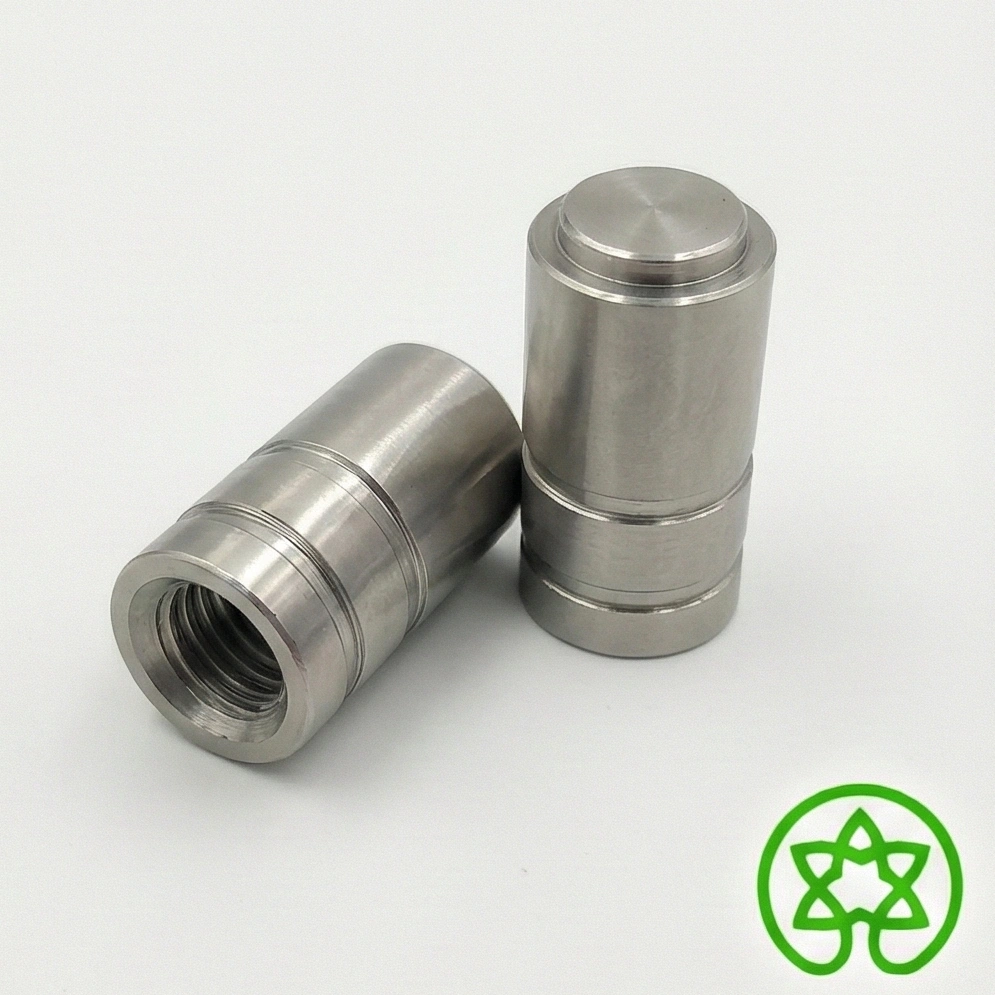
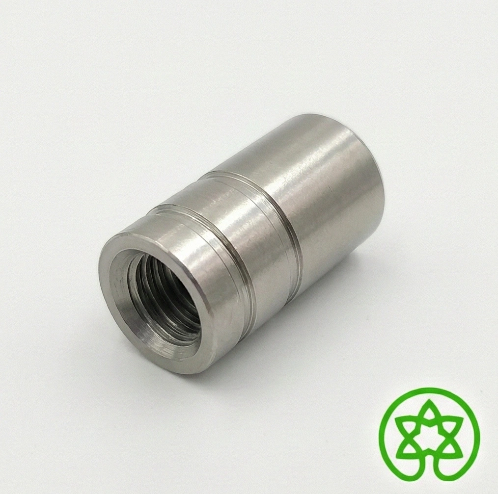
Hardened tool steel mold inserts are precision-machined, heat-treated steel components that form the cavity and core geometry inside a mold base. Rather than machining the entire mold from a solid block — which is costly and irreparable when worn — toolmakers use replaceable inserts for the critical forming surfaces. When an insert wears or is damaged, only the insert is replaced, dramatically reducing downtime and mold maintenance cost.

At OM Engineering Works, we manufacture custom CNC machined mold inserts for plastic injection molding, die-casting, rubber compression molding, and precision stamping applications. Our inserts are produced using advanced Traub machining job work, precision turned components capabilities, and custom engineered components solutions for toolrooms and OEM manufacturers.

Our Bhayandar, Mumbai facility is equipped with CNC turning centres, cylindrical grinding, surface grinding, jig boring, and EDM wire-cutting capability — covering the complete range of mold insert geometries from simple cylindrical bushings and gate inserts to complex lifter inserts, slider cores, and multi-contour cavity inserts.

Types of Mold Inserts We Manufacture:

  • Mold Cavity Inserts: Female impression inserts that form the outer surface of the molded part — machined to precise contour, draft angle, and surface finish specifications
  • Mold Core Inserts: Male forming inserts that create internal features, undercuts, and holes in the molded part — typically the most wear-critical element
  • Gate Inserts: Precision-bored inserts at the injection point — resists wash-out from high-velocity polymer flow, replaceable without scrapping the mold base
  • Sprue Bushing Inserts: Cylindrical inserts with precision-tapered bores for smooth sprue pull; made from hardened tool steel to resist erosion
  • Lifter & Slider Inserts: Moving mold components that release undercut features during ejection — require tight dimensional tolerances for smooth sliding and leak-free parting
  • Ejector Pin Hole Inserts / Bushings: Precision-bored hardened bushings that guide ejector pins and resist wear from millions of ejection cycles
  • Die-Cast Mold Inserts: H13 / SKD61 inserts for aluminium, zinc, and magnesium die-casting — thermal shock resistant, nitrided surface for extended life

Why Use Replaceable Mold Inserts?

  • Reduced Mold Maintenance Cost: Replace only the worn insert rather than rebuilding the entire mold — saves 60–80% on repair cost versus re-machining from solid
  • Shorter Downtime: Pre-machined spare inserts can be swapped in hours rather than waiting weeks for full mold rework
  • Design Flexibility: Multiple insert variants can be swapped into one mold base to run different part configurations — reducing tooling investment
  • Superior Surface Quality: Hardened and mirror-polished inserts produce consistently smooth part surfaces with no sink marks, flow lines, or mold release issues over millions of cycles
  • Improved Part Accuracy: Tight-tolerance hardened inserts maintain dimensional stability under the thermal and pressure cycling of high-volume production

Industries Where Our Mold Inserts Are Used:

Our Mold inserts serve plastic injection molding toolrooms, automotive stamping die shops, consumer electronics mold makers, medical device tooling, packaging cap molds, die-cast tool manufacturers, and rubber compression mold shops across India, Europe, the Middle East, and Southeast Asia.

Technical Details

Steel Mold Insert — Specifications

Dimensional & Machining Specifications

Tool Steel Grades P20 (1.2311), H13 (1.2344), D2 (1.2379), S7, O1, M2, NAK80
Manufacturing Process CNC Turning, CNC Milling, Surface / Cylindrical Grinding, Wire EDM, Jig Boring
Size Range (OD / Profile) 5 mm to 350 mm (custom sizes beyond on request)
Length Range 5 mm to 500 mm
Dimensional Tolerance ±0.005mm (profile) | ±0.002mm (bore / ground fit)
Roundness / Cylindricity 0.003 mm (ground components)
Surface Finish — Cavity Ra 0.05 μm (mirror polish, SPI A1/A2) to Ra 0.8 μm
Surface Finish — Core Ra 0.2 to Ra 0.8 μm depending on application
Draft Angles 0.5° to 5° (as per drawing / mold design)
Fitting Standard H6/h5 (precision sliding fit) | H7/g6 (standard fit)
Quality Standards ISO 2768-f (fine), First Article Inspection, CMM Report

Heat Treatment & Surface Treatment Specifications

Pre-Hardened Grades P20 / NAK80 — supplied at HRC 28–34 (no further HT needed)
Through Hardening H13 → HRC 48–52 | D2 → HRC 58–62 | O1 → HRC 60–62
Vacuum Hardening Available for H13, M2 — minimises distortion and decarburisation
Nitriding / Nitrocarburising Surface hardness HV 900–1100 (die-cast inserts, gate inserts)
PVD / TiN Coating TiN, TiAlN, CrN — 2–4 μm coating for extended wear life
Electroless Nickel Plating 20–50 μm for corrosion resistance and demold release
Hard Chrome Plating 25–75 μm for wear resistance on runner and gate surfaces
Post-HT Distortion Control All inserts re-ground after heat treatment to restore tolerance
Tempering Cycles Double tempering on request for stress relief and toughness
Certifications Available EN 10204 3.1 MTC, Hardness Test Certificate, CMM Report, CoC
Our Expertise

How We Manufacture Precision Mold Core & Cavity Inserts

01
Drawing Review & DFM Analysis

On receipt of your 3D STEP model or 2D drawing, our engineering team reviews the insert geometry for manufacturability — checking draft angles, minimum wall thickness, undercut releasability, radius constraints, and surface finish requirements. DFM feedback is provided within 24 hours if any features require modification for optimal tooling life or machinability.

02
Tool Steel Procurement & Incoming Inspection

Certified tool steel bar or block sourced from premium mills — Böhler (Austria), Uddeholm (Sweden), or accredited Indian suppliers — with EN 10204 3.1 Material Test Certificates. Chemical composition verified via spectrometer. Incoming hardness and dimensional checks on all stock before machining begins. Heat number traceability maintained throughout.

03
Rough Machining (Soft State)

Inserts are rough-machined in the annealed (soft) condition using CNC turning centres or CNC milling. Rough stock allowance of 0.3–0.5 mm is left on all critical surfaces. Coolant management is carefully controlled to prevent thermal stress in tool steel during roughing. Features such as cooling channels, O-ring grooves, and mounting bores are completed in this stage.

04
Heat Treatment — Hardening & Tempering

Inserts are sent for vacuum hardening (preferred for minimum distortion) or conventional salt-bath hardening at our approved heat treatment partner. H13 is taken to HRC 48–52, D2 to HRC 58–62, O1 to HRC 60–62 with double tempering for stress relief. Hardness verified on every insert with Rockwell tester post-treatment. Distortion is documented and factored into the subsequent grinding allowance.

05
Precision Grinding & Finish Machining

Post-hardening, all critical dimensions are finish-ground using our in-house CNC machining infrastructure and inspection facilities. on cylindrical grinding machines (for round inserts) or surface / jig grinding (for profiled inserts). Wire EDM is used for intricate contours, thin ribs, and sharp inside corners. Final dimensions held to ±0.005mm. Fitting diameter ground to H6/h5 class for precise locate and seat in the mold base.

06
Mirror Polishing, Inspection & Dispatch

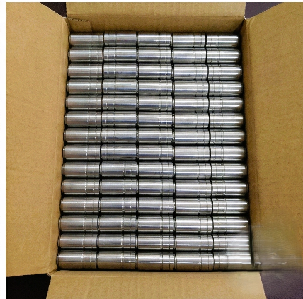
Cavity surfaces are progressively polished from 400 grit through 800, 1200, 1500 to diamond compound — achieving SPI A1/A2 mirror finish (Ra 0.05 μm) for optical and cosmetic-grade molds. 100% CMM dimensional verification. Surface roughness measured with profilometer and documented. Inserts wrapped in VCI anti-rust film, individually labeled, and packed in foam-lined export cases. Full CMM report and hardness certificate dispatched with the shipment.

Machines & Equipment

  • CNC Turning Centres with live tooling
  • CNC Milling (3-axis profiling)
  • Cylindrical & surface grinding machines
  • Wire EDM (for intricate contours)
  • Jig boring machine (precision bore location)
  • CMM — 3D dimensional verification
  • Surface profilometer (Ra measurement)
  • Hardness tester — Rockwell & Vickers

Quality Control

  • First Article Inspection (FAI) with CMM report
  • 100% hardness verification post heat treatment
  • Surface roughness Ra measured per insert
  • Fitting diameter Go/No-Go gauge check
  • Optical comparator for contour verification
  • EN 10204 3.1 MTC on all tool steel grades
  • VCI anti-rust packaging for export dispatch
Material Options

Tool Steel Grades for Precision Mold Inserts

P20 / 1.2311 (Pre-Hardened Mold Steel — HRC 28–34)

Properties: Delivered in pre-hardened condition (HRC 28–34), excellent machinability, good polishability, no post-machining heat treatment required. Ideal for medium-volume production molds (up to 500,000 cycles).

Best For: Plastic injection mold cavity and core inserts for medium-volume production, prototype molds, consumer goods packaging, general engineering mold components.

Standards:

DIN 1.2311 AISI P20 IS 103Cr1 Böhler M238

H13 / 1.2344 / SKD61 (Hot-Work Tool Steel — HRC 48–52)

Properties: Chromium-molybdenum-vanadium hot-work tool steel with excellent thermal fatigue resistance, toughness, and resistance to heat checking. The benchmark material for die-casting inserts and high-temperature molding.

Best For: Aluminium and zinc die-cast mold inserts, hot runner gate inserts, high-volume plastic injection mold cores (1M+ cycles), rubber mold inserts, extrusion tooling.

Standards:

DIN 1.2344 AISI H13 JIS SKD61 Uddeholm Orvar

D2 / 1.2379 (Cold-Work Tool Steel — HRC 58–62)

Properties: High-carbon, high-chromium cold-work tool steel with exceptional wear resistance and compressive strength. Achieves HRC 58–62 after hardening. Excellent for abrasive plastic materials and long-run high-wear insert applications.

Best For: Mold inserts for abrasive glass-filled, mineral-filled, or flame-retardant plastics; stamping die inserts, punches and blanking inserts requiring extreme wear resistance.

Standards:

DIN 1.2379 AISI D2 IS T215Cr12 Uddeholm Sverker 21

S7 / NAK80 / O1 — Specialty Tool Steels

Properties: S7 is a shock-resistant tool steel with exceptional impact toughness (for inserts prone to cracking). NAK80 is a pre-hardened maraging steel (HRC 40–43) with superior polishability for optical-grade mirror finishes. O1 is an oil-hardening tool steel with fine grain structure for tight-tolerance inserts.

Best For: S7 — sliding cores, lifters, and thin-section inserts prone to chipping; NAK80 — optical lens mold inserts, cosmetic part molds requiring SPI A1 mirror polish; O1 — prototype inserts, jig components.

Standards:

AISI S7 NAK80 (Daido) AISI O1 Böhler W300
Applications

Industries Using Our Precision Mold Core & Cavity Inserts

Plastic Injection Molding

Cavity inserts, core inserts, gate inserts, sprue bushings, runner inserts — for single and multi-cavity molds producing consumer, industrial, and automotive plastic parts

Automotive Tooling

Bumper mold inserts, interior trim cavity inserts, under-hood component cores, lighting lens mold inserts, rubber seal compression mold cavities

Die Casting

H13/SKD61 inserts for aluminium, zinc, and magnesium die-casting tooling — heat-checking resistant, nitrided for extended life, precision-fit to die base

Medical & Pharma

FDA-compatible mold inserts for syringes, vials, caps, and diagnostic device components — mirror polished, cleanroom-packaged, with full material traceability

Consumer Electronics

Smartphone housing mold inserts, connector body cavity inserts, keyboard cap mold cores — mirror polished for cosmetic-grade surfaces on visible plastic parts

Packaging & Closures

Bottle cap mold inserts, thin-wall container cores, tamper-evident closure cavity inserts — high-speed production inserts for hundreds of millions of cycles

Stamping & Press Tools

D2 / M2 punches, blanking die inserts, progressive die components — extreme wear resistance for high-speed sheet metal stamping and forming applications

Rubber & Compression Molding

O-ring mold inserts, gasket compression mold cavities, silicone part mold cores — H13 or D2 with nitrided surface for chemical resistance and long service life

Product Comparison

OM Engineering vs Alternative Mold Insert Suppliers

Feature / Capability OM Engineering Works Typical Indian Supplier Off-the-Shelf / Catalogue Insert
Dimensional Tolerance ±0.005mm (CMM verified) ±0.02 – 0.05mm ±0.02mm (standard only)
Tool Steel Grades P20, H13, D2, S7, NAK80, O1, M2 P20 or H13 only Standard grades, no choice
Custom Geometry Fully custom to 3D model / 2D drawing Limited complex profiles Standard shapes only
Surface Finish Ra 0.05 μm mirror (SPI A1/A2) Ra 0.4 – 0.8 standard Ra 0.8 – 1.6
Hardness Range HRC 28–62 (grade dependent) HRC 30–52 typical Fixed hardness only
Heat Treatment Vacuum hardening, nitriding, PVD coating Conventional hardening only Pre-hardened only
Lead Time (Sample) 7–14 working days 20–35 days 45–90 days (import)
Documentation CMM report + MTC + hardness cert + CoC Basic cert only Minimal documentation
Common Questions

Custom Mold Insert — FAQs

A mold insert is a separate, precision-machined component fitted into a mold base that forms the critical cavity or core geometry. Instead of machining the entire mold from one solid block — which is expensive and irreparable when the forming surfaces wear — toolmakers design molds with replaceable inserts for the high-wear contact zones. When an insert wears or is damaged, only that insert is replaced (typically in hours), rather than scrapping or rebuilding the entire mold. This approach saves 60–80% on mold maintenance costs and reduces production downtime. Inserts also enable running different part variants in a single mold base by simply swapping insert sets.

The choice depends on production volume, plastic material type, and surface finish requirements. P20 (HRC 28–34, pre-hardened) is ideal for low-to-medium volume molds (up to ~500,000 shots) with standard unfilled plastics — it's easy to machine, weld-repair, and polish, making it the most cost-effective choice for prototype and medium-run tooling. H13 (HRC 48–52 after hardening) is the industry standard for high-volume molds (1M+ shots), hot runner systems, and gates subject to thermal cycling — its toughness prevents cracking under the thermal stresses of injection molding. D2 (HRC 58–62) is chosen for abrasive plastics such as glass-filled nylon, mineral-filled PP, or flame-retardant ABS — its extremely high wear resistance extends insert life dramatically over H13 in these applications. We advise on grade selection based on your specific part material, production volume, and mold design.

We achieve the full SPI (Society of the Plastics Industry) surface finish range: SPI A1 / A2 mirror polish (Ra 0.025–0.05 μm) for optical-grade, high-gloss cosmetic surfaces using diamond compound; SPI B1 / B2 semi-polish (Ra 0.1–0.2 μm) using 600 grit paper for general engineering finishes; SPI C1 / C2 stone finish (Ra 0.4–0.8 μm) for functional non-cosmetic surfaces; and SPI D1 / D2 bead blast or EDM textured finishes for grip surfaces and structured part appearances. Surface roughness is measured with a calibrated profilometer and the Ra value documented on the inspection report with every insert.

Our mold inserts are supplied at hardness levels appropriate to the chosen grade: P20 at HRC 28–34, H13 at HRC 48–52, D2 at HRC 58–62, and O1 at HRC 60–62. Hardness directly determines wear life — a harder insert surface resists abrasion from plastic flow and maintains its dimensional and surface finish integrity over more production cycles. However, higher hardness also reduces toughness, making the insert more susceptible to chipping under impact or thermal shock. H13 at HRC 48–52 represents the optimal balance of wear resistance and toughness for most injection molding applications. Every insert is hardness-tested with a calibrated Rockwell tester and the result documented on a hardness certificate supplied with the insert.

Yes — we manufacture hardened mold inserts from: 3D CAD models (STEP, IGES, Parasolid, SolidWorks .SLDPRT), 2D engineering drawings (PDF, DXF, DWG), or physical sample inserts for reverse engineering (we perform CMM scanning to generate a manufacturing model). For complex insert profiles with contoured parting surfaces, lifter geometry, or multi-axis features, 3D STEP models are strongly preferred to eliminate ambiguity. Our engineering team reviews your model, provides a detailed quotation within 48 hours, and manufactures a first article sample with a full CMM dimensional report for your approval before batch production begins.

Nitriding is a thermochemical surface hardening process that diffuses nitrogen into the steel surface at 480–560°C, producing a very hard nitride layer (HV 900–1100, approximately HRC 67–70 equivalent surface hardness) without significant dimensional distortion. Unlike through hardening, nitriding is performed on the already-finished insert — the dimensional change is typically 0.01–0.02 mm, which is factored into the pre-nitriding machining allowance. Nitriding is specified for: die-cast mold inserts (where liquid aluminium or zinc directly contacts the insert surface); gate and sprue inserts subject to high-velocity melt erosion; runner strips experiencing frequent abrasive contact; and any mold component where surface hardness beyond the through-hardened capability of the base grade is required. We coordinate nitriding through our approved specialist partners and supply inserts with a nitriding depth and hardness report.

Yes, OM Engineering Works regularly exports precision Mold inserts to toolrooms and mold manufacturers in the USA, UK, Germany, Netherlands, UAE, Malaysia, Singapore, Thailand, and Australia. We have experience with all export documentation requirements including commercial invoice, packing list, certificate of origin, and EN 10204 3.1 material certificates. All inserts are individually wrapped in VCI anti-rust film, fitted with protective end caps, and packed in foam-lined wooden or plywood export cases to prevent dimensional damage in transit. Lead times for export orders range from 14–21 working days depending on complexity and quantity.

There is no minimum order quantity for custom hardened mold inserts — we accept single-piece orders for toolroom replacement inserts, prototype mold components, and first article samples. We also supply ongoing repeat orders (spare insert sets) and batch production for multi-cavity mold programs. Single-piece and small-batch orders receive the same quality attention — full CMM inspection report, hardness certificate, and CoC — as large production runs. Contact us with your drawing or 3D model for a no-obligation quotation.

Heat treatment distortion in tool steel inserts occurs due to: (1) release of machining stresses during the high-temperature austenitising cycle; (2) volumetric expansion during martensite transformation on quenching; and (3) thermal gradients across the insert cross-section during rapid cooling. We control distortion through: rough machining with generous stock allowance (0.3–0.5 mm on critical surfaces); specifying vacuum hardening where possible (uniform heating and slow gas quench minimises thermal gradients vs salt-bath or air-blast quench); stress relief tempering between rough and finish machining for large inserts; and leaving all tight-tolerance features (bores, fitting diameters, contoured surfaces) for post-hardening precision grinding. Actual distortion on each insert is measured and documented, and all critical dimensions are re-ground to specification after heat treatment.

We provide: EN 10204 3.1 Material Test Certificate (chemical composition and mechanical properties from the steel mill); First Article Inspection (FAI) Report with full CMM dimensional measurements vs drawing tolerances; Hardness Test Certificate with Rockwell HRC values measured on each insert; Surface Roughness Report with Ra values at specified locations (for mirror-polished and ground surfaces); Nitriding Depth & Hardness Certificate (where applicable); Certificate of Conformance (CoC) confirming the insert meets all drawing requirements; and PVD / TiN Coating Certificate with thickness measurement (where coating is specified). All documents are dispatched digitally (PDF) on the same day as shipment.
Related Capabilities

Explore Our Other Precision CNC Manufacturing Services

Precision Turned Components

CNC turned stainless steel, brass, alloy steel precision parts for automotive, hydraulic, and industrial OEM applications.

Traub Machining Job Work

High-volume Traub machine components with tight tolerances and repeatable batch production capability.

Rapid Prototyping & Small Batch CNC

Low MOQ prototype and development batch machining for new product tooling and mold validation.

Need Precision Hardened Mold Inserts Manufactured to Your Drawing?

Share your 3D model (STEP) or 2D drawing — receive a detailed quote within 24–48 hours. Single piece to production batches. P20 · H13 · D2 · S7 grades available. CMM report + hardness cert + MTC provided with every order. Mumbai-based manufacturing, globally exported.

Get Mold Insert Quote!